Pre-preg Composite Manufacturing Machine Project
Contributors: Matthew Galarza, Aura Cardona, Anthony Herrera, Jailin Cao, Anton Kapitman, Kevin Yan, and Billy Konstantinou
Part I: Fiber Spreader
Executive Summary
In general, it is difficult for companies to order small order quantities of composite prepreg as minimum order quantities from manufacturers are high due to skews created from primary prepreg markets. In this case, Douglas Outdoors, an award-winning fishing rod manufacturer has sponsored this team to help address this problem. The proposed solution is a miniaturized prepreg machine which would give Douglas Outdoors the ability to produce their own prepreg material in-house. This machine is designed to take in a roll of the raw composite tow material, for which it will then pass through 2 systems that control the spreading of the material and eventually the impregnation, resulting in a roll of carbon fiber prepreg that is ready to be used or stored for later.
This report focuses specifically on the development and testing of the spreading process that occurs in this machine. Research was first conducted to understand the state of industry and identify any relevant information in regards to fiber spreading. Through this useful information was deducted on the mechanics behind the spreading process which provided a starting point for development of the system. Creation of this system first began with the designing of the fiber spreading unit which houses the spreader pins in charge of the actual spreading effect, as well as the designing of the pins themselves. In the case of the spreader unit, various concepts were generated with the main goal of allowing easy adjustability of the spreader pins between test runs. Various equations for these pins were created to test the effect that the different geometries had on not only the system's ability to spread the tow but also their effect on uniformity. For the sake of testing, many of the system components used in the final design utilize 3D parts made out of PLA material. This allowed for a simplistic manufacturing process, and in terms of the pins, 3D printing allowed for rapid development of different pin geometries after gaining insight from running tests. Tests that were conducted utilized a standard setup and the parameters used were determined on the basis of ensuring reproducibility and eliminating any outside sources of error. Results from these tests were promising for this iteration of the design, and allowed for correlations to be drawn regarding the spacing on the spreader pins, as well as trends related to the pin sizes used. Based on this data, the next steps for the project will be identified.
Background and Motivation
In general, it is difficult for companies to order small order quantities of composite prepreg as minimum order quantities from manufacturers are high due to skews created from primary prepreg markets like aerospace and defense. Prepregs are also generally not made in-house and need to be sourced directly from the prepreg manufacturer, forcing companies to become fully reliant on 3rd parties which can limit certain aspects of product production and product development. For the case of the project's sponsor company, Douglas Outdoors, this has been their same experience. To address this issue, the objective of the overarching project is to design and prototype a small scale prepreg machine which will allow companies like Douglas Outdoors to produce their own batches of carbon fiber prepreg and eliminate the need to outsource these materials.
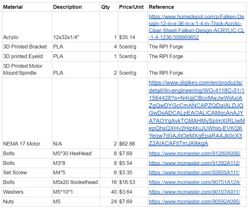
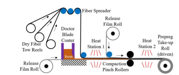
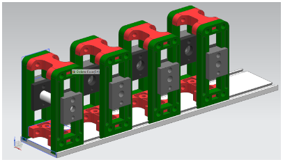
This proposed prepreg machine is composed of two main systems, both which are essential for production of the product: the fiber spreader and the impregnation station. The machine is meant to operate by taking reels of dry carbon fiber reels, called tows, and pulling these tows through the fiber spreader. Within this fiber spreader the tow is passed over a series of stationary pins which induce a spreading effect along the tow's width, making it overall flatter while also oriententing the individual fibers in a uniform manner. The pins themselves, designated as "spreader pins", utilize a type of convex geometry which is the driving mechanism for the divergence of these fibers. When a force is applied to the end of the tow, tension is created within the strands further pushing the tow down into these pins to create this spreading effect. Now having a spread uniform tow, the carbon fiber continues to the impregnation station where it is dipped into a resin bath to "impregnate" the fibers. Fully saturated with resin, all excess material is removed via a squeegee after which a series of heat lamps partially cure the prepreg. At this time, the release film is placed on both sides of the prepreg to prevent sticking and the prepreg is re-rolled to be used or stored for later on. An overall overview of this system can be seen below in Figure 1.
The part of the project assigned to this group regards development of the fiber spreader system which is very critical to the end product that will be outputted by the machine. As received from the manufacturer, the individual fibers within the tow can be organized in a sporadic and unpredictable manner, making it unideal for any impregnation process. For such a process, uniformity is key in order to get the desired strength and material characteristics from the carbon fiber while also ensuring consistency between batches. The spreading and orienting of these fibers allows for greater resin impregnation and eliminates cases where sections of the tow see varying amounts of resin coverage. Given this, development of the fiber spreader system will be key to the successful completion of this project.
Goals and Deliverables
The overall goal for this project was for the project team to design a fully functional fiber spreader unit that could be used to spread the 24K carbon tow for better resin impregnation when the tow reaches the resin impregnation unit. This goal was separated into two large scale deliverables, where each deliverable had a list of needs and requirements. The deliverables were (1) Create a fiber tow spreading unit, and, (2) Design spreading pins. The needs and requirements for each deliverable are broken down in the list below.
1. Create a fiber tow spreading unit
        a. Unit has to allow for easy pin changes
        b. Unit has to allow for several pin placement locations
        c. Unit has to completely fix the spreading pins once mounted
        d. Unit has to be able to keep the tow centered as the reel unravels
        e. Unit has to secure the given 24K tow reel so it can be rotated but not translated
        f. Unit has to provide rotational resistance to keep the tow taught as is pulled
        g. Unit has to be able to be secured to a surface
        h. Unit has to be modular and portable
2. Designing spreading pins
        a. Pins have to have quantifiable curve based on equation
        b. Pins have to spread the fiber tow
            i. Final width must increase from original value
        c. Pins have to be easily mounted into the fiber tow spreading unit
        d. Pins have to cause minimal fraying of the fiber
Each of these needs and requirements needed to be met during the design process for both deliverables and guided the team throughout the design process. The entirety of the concept generation and design process will be discussed in the Concept Generation/Design section below.
Concept Generation and Design
The first deliverable that the team worked on was deliverable one, creating a fiber tow spreading unit. Deliverable two could not be worked on until the completion of deliverable one because the spreading pins needed to be able to be mounted into an overall spreading unit in order to conduct experimental testing on the pins. The design of the spreading unit was broken up into several steps, each of which addressed one or more of the requirements defined in the Goals and Deliverables section above. This allowed the team to mix and match generated ideas from each step in order to design the best final product. The first aspect of the spreading unit that was designed was the overall structure and the way that the pins would be secured into that structure. This aspect of the design addressed requirements 1a-c, 1g, and 1 h.
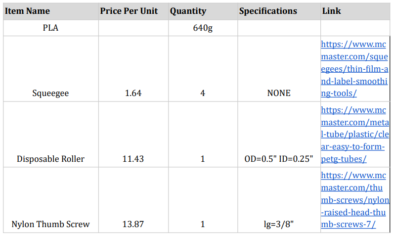
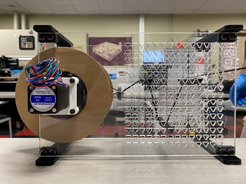
Two designs which meet the aforementioned requirements through different means were generated for this portion of the spreading unit and are Figures 2 and 3 below. The matrix design (Figure 2) consists of two walls made of 1/4" acrylic spaced 4.13 inches (105 mm) apart by four spreaders attached to all four corners of the walls. The use of spreaders lightened the final weight of the design while reducing the material cost of the unit. In addition the spreaders could be secured to a flat work surface through the use of clamps meaning that the design met requirements 1g and 1h. The slide design (Figure 3) consists of several pin holders (red and green structures in Figure 3) that are mounted on a rail through the use of dovetail slots. The distance between each side of the pin holders is set by how wide the red sections of the pin setups are designed. The design can be changed based on the needs of the system and can be reprinted allowing for wider red sections to be swapped in if needed. The rail the pin holders dovetail into would also have to be swapped out for a wider rail with dovetail slots matching the new width between the sides of the pin holders. The entire slide design could be secured to a work surface with clamps or similar methods satisfying requirements 1g. The whole unit could also be disassembled and packed away, fulfilling requirement 1h.
Each matrix wall is identical, having a matrix of cutouts in them where the ends of the pins are meant to be secured. In the first iteration of the matrix the cutouts were circular but in the final design triangular cutouts were utilized instead so the pins would not be able to rotate once they were mounted between the walls. The matrix design allowed the pins to be swapped easily while also allowing for limited horizontal and vertical positioning of the pin. The "resolution" of pin movement is limited to how close together the cutouts are located, which was .5 inches (12.7 mm) both vertically and horizontally in the final iteration. This matrix wall design ultimately satisfied requirements 1a-c. The slide design allows for pins to easily be mounted into the pin holders by securing each end of the pin into the gray vertical slider in each pin holder. This grey slider can then slide vertically by any increment, and the entire pin holder assembly can move horizontally along the rail by any increment. The only limits to the vertical and horizontal distance between pins is the total height of the pin holder and the length of the rail respectively. This design satisfies requirements 1a-c.
The design that was ultimately chosen was that of the matrix and was due to the fact that it was faster to manufacture and assemble the matrix design than it would be to manufacture the components of the slide design. In addition, while the slide design did have the better "resolution" of pin movement, it was determined that the matrix would be more than enough for the team's pin tests later on. The second aspect of the spreader unit that the team focused on was the method by which the tow reel would be secured to the system. This aspect of the design had to meet requirements 1d-f in order for the complete design to meet the needs and requirements of this deliverable. There were three concepts generated that would secure the tow reel to the spreader unit. A sketch of all three concepts is shown in Figures 4, 5, and 6 below.
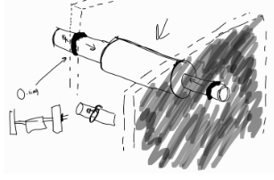
The o-ring and spacer design both utilize a spindle that the reel is placed and secured on. The spindle would have been press-fitted into the reel so that once the reel was placed on the spindle, the reel could not spin around the spindle. Instead in order to unravel the reel, the entire spindle would have to turn. The spindle would be centered in the spreader unit and because the reel would be centered and fixed on the spindle, the reel would be unable to translate in any dimension. These aspects of the spindle would satisfy requirement 1e. The o-ring design would satisfy requirement 1f through friction between the o-ring and the wall of the spreader unit. In this design, each end of the spindle would have an o-ring around it, pushed flush against the outside of the wall of the spreader unit (pictured in Figure 4). As the tow was pulled taught, the reel/spindle unit would begin to spin and unravel, this would cause the o-rings to also rotate. However, because they would be pressed flush against the wall, as the o-ring spun, friction would cause resistance against the rotational motion of the spindle. This would allow the tow to remain taught as the tow was pulled through the rest of the system.
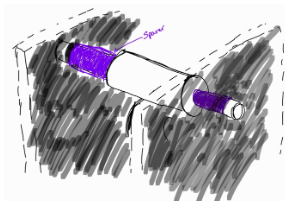
The spacer design generated resistance against rotation using a similar method, but instead of generating friction between an o-ring and the outsides of the spreader unit walls, friction was generated between the edge of each spacer and the insides of the spreader unit walls. On each leg of the spindle, a plastic sleeve called a spacer would be placed in order to keep the spindle from being able to move horizontally. The spacers would be flush with the inside of the spreader unit wall and one side of the reel, so that if the spindle was to spin, the spacer would also rotate. Because the spacer would be rotating against the inside wall of the spreader unit, there would be friction and a resistance against rotation that would keep the fiber tow taught satisfying requirement 1f as well. Neither the o-ring design or the spacer design were selected even though they met all the requirements necessary. This is because both the o-rings and the spacers would experience wear caused by the friction they experience while the reel is spinning. This would eventually impact the performance of the unit as the o-ring and spacer would wear down at some point in time (actual time would depend on the frequency and duration of system use) thus producing less resistance against rotation as the system was used. This would impact performance and require the spacers and o-rings to be replaced often to mitigate this impact. Instead of these designs, the pinch design was selected as the method to secure the reel to the spreader unit.
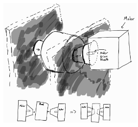
The pinch design consists of two conical sections inserted through the walls of the spreader unit (through a hole with clearance around it) and into the center of the reel. Because the sections are conical, the reel will self-center as the sections are pushed closer together. The sections would be pushed in hard enough that the reel would be unable to spin around the sections but would instead spin with the sections like the spindle did in the o-ring and spacer designs. Mounted on each section would be a stepper motor that would be the source of rotational resistance. Every motor has an internal resistance and can be programmed to provide additional resistance if needed allowing them to be used under a variety of conditions including some where the pulling force of the tow may vary. The use of the motors would satisfy requirement 1f while use of the cones would satisfy 1e. Any wear that the motors would experience would be minimal (motors are designed to spin for long periods of time) and there would be no wear on the conical sections as they are not rubbing or sliding against anything since everything is secured tightly to them. This is why this option was selected as the method to secure the reel to the spreader unit.
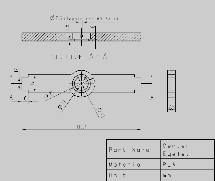
The last requirement to be satisfied in the spreading unit is 1d, where the unit has to keep the fiber tow centered as the reel unravels. This was a relatively simple problem due to the matrix design that was chosen. A centering eyelet was designed so that it could be secured to the system by slotting it into a cutout in the walls of the spreading unit. The centering eyelet would have a hole in the center that would be threaded with the fiber at the beginning of the reel. As the reel unraveled, all the fiber would travel through the eyelet, centering the tow in the process. The initial design of the eyelet, shown by Figure 7a, was such that there was a pin with a hole in the center where the edges were to prevent fraying of the tow as it passed through. The final design, shown by Figure 7b, was one where instead of chamfering the edges of the eyelet, a machined metal eyelet could be inserted and secured into the pin instead, allowing for different eyelets of different geometries to be used in the spreading unit.
The final deliverable required for this project was the design of the pins. A crucial component of the project, the pins dictated fiber spreading, so careful designs were required to ensure correlations could be made between mathematical descriptions and physical observations. To tackle this challenge, pin geometries would be generated through mathematical equations allowing for robust parameter testing. Through research and initial fiber manipulation, it was determined that curved geometries lead to the greatest amount of fiber spreading and therefore, geometries featuring these curvatures should be modeled. Multiple shapes were considered, however, parabolic and elliptical cross-sections were deemed the most appropriate for pin designs and can be seen in Figure 8 below.
Both geometries featured the ability to alter curvature significantly which was ideal for testing, however, the elliptical cross-section had more governing parameters that allowed for greater manipulation. Equation 1 below is the equation of the ellipse used for pin creation.
By keeping certain parameters constant, the curvature of the ellipse could be adjusted without requiring changes to other pin dimensions such as length and height. For pin curvature, b in Equation 1 above acts as a scaling term which can be manipulated to create a variety of pin curvatures. A finalized pin model can be seen in Figure 9 below. In this design, stoppers were added to both ends of the pins to assist in testing setup.
Manufacturing and Assembly
We took the concept from the previous section and refined the prototype design to allow the parts to be manufactureable with rapid prototyping techniques. The parts drawings, and bill of materials are attached in the Figures below. A full component list can be found in the appendix below.
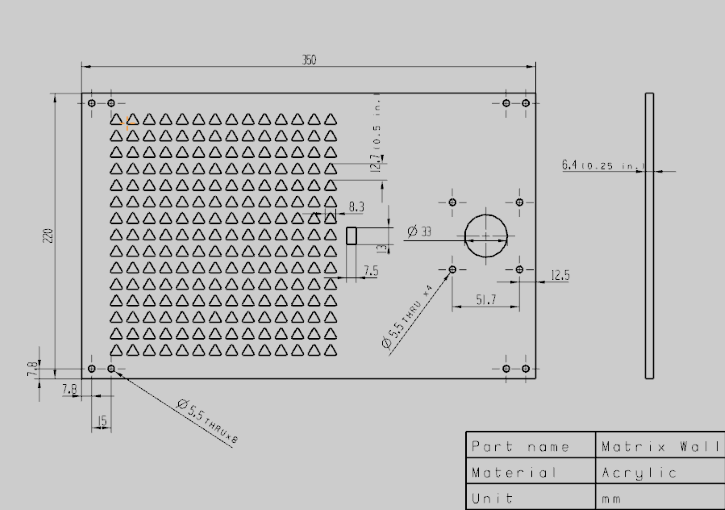
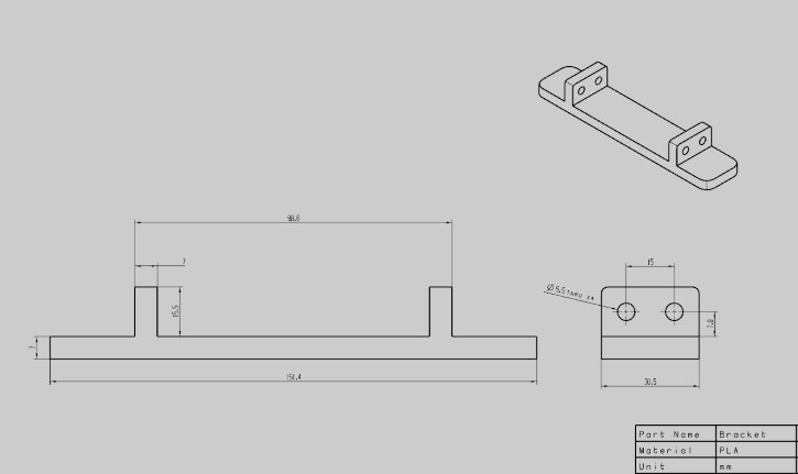
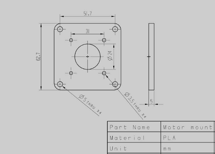
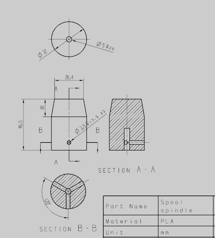
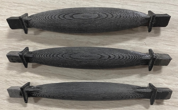
To manufacture the prototype, two matrix walls are cut out of a sheet of 0.25 in thick acrylic with a laser cutting machine. The rest of the customer parts including wall brackets, motor mounts, and spool spindle are 3D printed with 0.2mm layer height, 0.6mm wall thickness and 30% infill. Spreader pins are 3D printed with 0.2 mm layer height, 1mm wall thickness and 45% infill. The printed spreader pins are sanded with sandpaper to smooth out the layer line artifact from 3D printing. The unsanded pins are shown in Figure 15 below and a sanded spreader pin is shown in Figure 16 below.
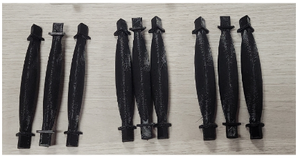
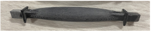
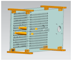
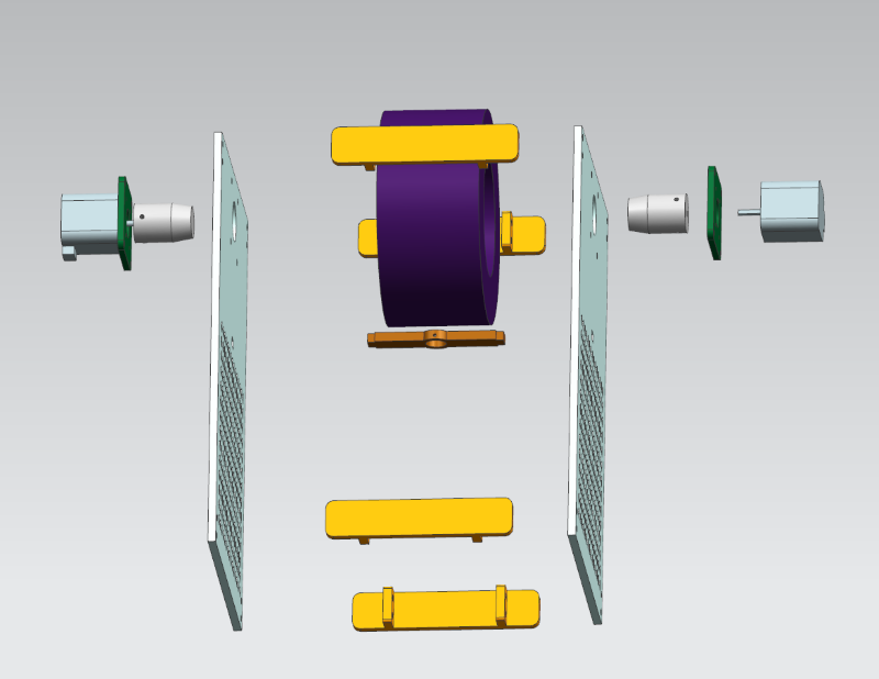
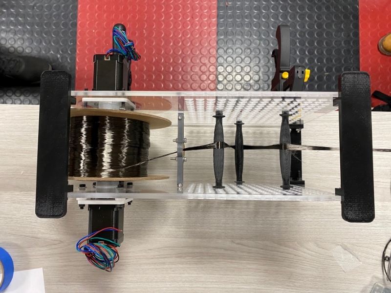
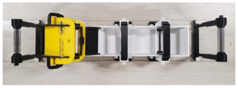
Figure 17 below shows an exploded view of the CAD model of the prototyped machine. Figure 18 and 19 shows the assembled final prototype.
Experimental Testing Setup
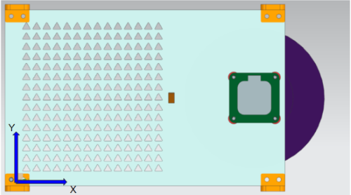
The goal of experimental tests were to determine the effectiveness of elliptical pin geometries as well as observe correlations between geometric changes and fiber spreading. In order to ensure collected data and observations are accurate to particular parameters, careful testing setup is required. In order to remain consistent during testing, pin locations were fixed at specific triangle locations within the lattice seen in Figure 20 below. The triangular section was superimposed over an xy-axis with each pin corresponding to a location within the grid.
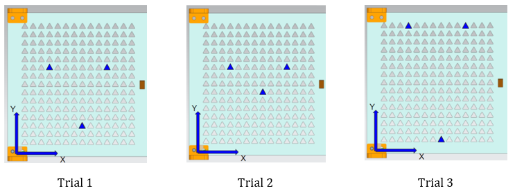
For each pin geometry tested, three trials were run, each with a varied set of pin locations which can be seen in Figure 21 below. The first trial had pins oriented in a random median position, similar to literature reviewed during initial project research. The second trial moved the center pin upward four positions while keeping the first and third pin fixed. The third trial placed the pins at the extremes of the grid with the first and third pins located along the top of the y-axis and the center pin along the bottom.
It should be noted that pin testing does not include horizontal changes along the x-axis as individual pin changes had shown to cause significant variability in results. This is attributed to the fibers angle of attack to the pin as horizontal locations change. Therefore, movement horizontally of a single pin will change the angle of attack of the others, making data unreliable and misleading. As stated above, the pin geometries selected were of elliptical shape with a variation in curvature caused by a scaling term, b. As seen above in Equation 1, the term dictates the slope of the ellipse height and therefore, if all parameters are kept constant, will affect only curvature. A total of three pins will be tested with each test consisting only of pins with the same scaled factor. These pins, shown in Figure 22 below, have the scaling factors of 0.3, 0.4, and 0.5, respectively.
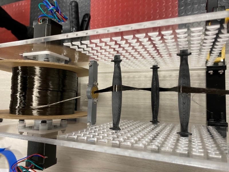
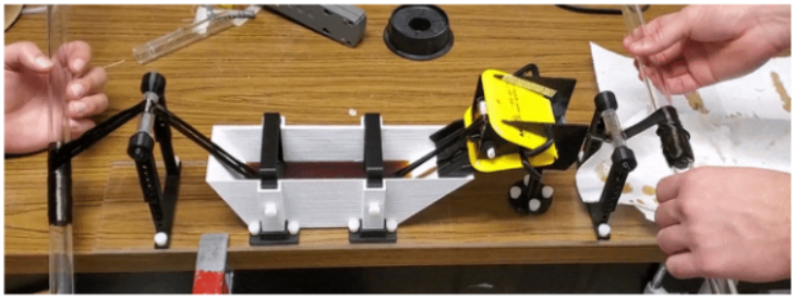
Prior to testing, certain boundary conditions and assumptions were made to ensure repeatable trials. First, the tension applied to the fiber was the internal resistance of the stepper motor when only two of the leads were connected. This provided adequate tension without straining the pins or placing an excessive burden on the tow. Furthermore, it was assumed that the tension applied was constant as the fiber unraveling from the tow did not contribute significantly to the decrease in the radial distance of torque. Second, the fiber was pulled an average of six feet per trial to ensure spreading had reached steady state prior to data collection. To begin testing, pins are inserted into the grid for the given trial with the eyelet and reel fixed at their positions. The opposite acrylic panel is then aligned and fixed into place by black connectors seen in Figure 18 below. A small segment of the tow is then unraveled, fed through the eyelet and then along the pins. Once secured, the motor leads are connected and the fiber is pulled through the device in a straight manner. The fibers are drawn until steady state is achieved, where measurements and data can be collected.
Results
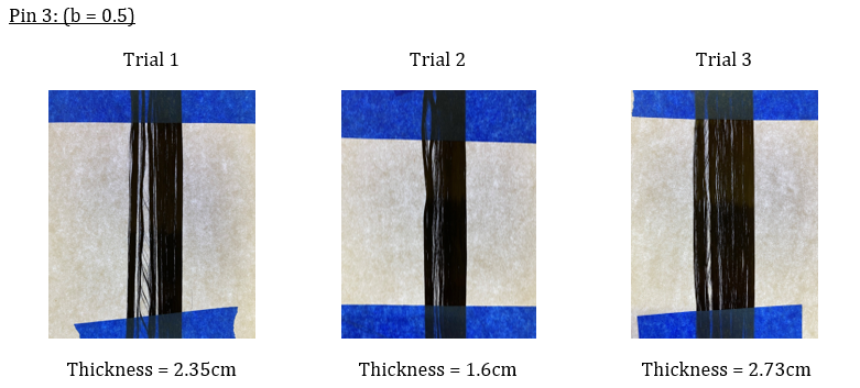
All the results below are of pins with separate scaling factors, tested in three trials with variations in pin location. Procedures were kept constant for all trials and testing was terminated at steady state.
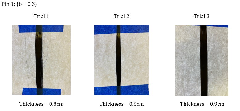
During trial 1, an irregularity caused by 3D printing was not removed when sanded and had cut some fibers during testing resulting in fraying. Trial 2 had negligible spreading compared to initial tow thickness. Trial 3 produced the best spreading, close to double the initial tow thickness, 0.5cm.
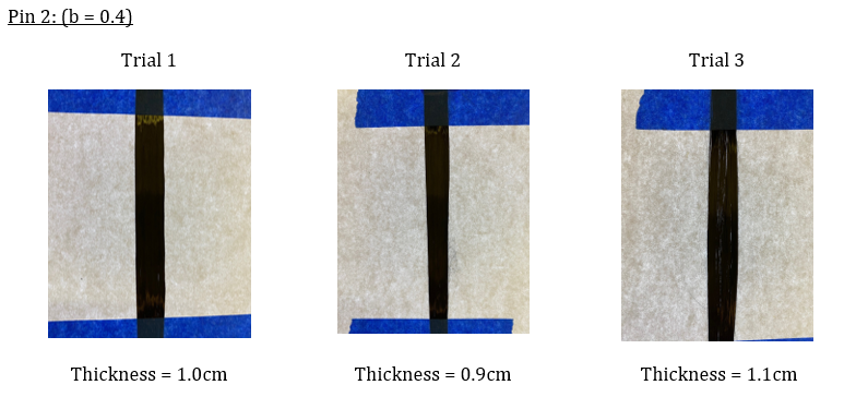
Overall, even spreading was observed from all trials, however, desired tow thickness and visibility was not achieved. As curvature increased, it can be noted that spreading did improve.
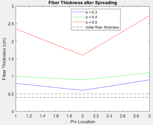
The final trial conducted had shown significant improvements in fiber spreading. The increased pin curvature correlated well with fiber spreading and had shown improvements in desired thinned sections. Similarly to pin 1, unsmoothed sections had contributed to fiber breaking as seen in trial 1 with large separated sections. The data collected from the experiments not only met project requirements but also provided insight into fiber spreading. From the data, certain correlations can be made about pin curvature and distance as seen in Figure 24 below. It can be seen that increasing the curvature of pins led to greater fiber spreading and more evenly distributed fiber sections. Furthermore, greater distances between pins aided in spreading. This was observed during testing as the fibers were able to develop for longer periods of time before making contact with the next pin in the sequence. To further this observation, pins that were closer together had worse spreading results throughout all trials, regardless of pin dimension.
Conclusion and Next Steps
Testing highlighted a lot of useful information which gave indication on what kind of future tests to run as well as other tests/techniques that might be beneficial to run in the future. In testing it became clear that the smoother we were able to get the spreading pins, the more problems we actually encountered during tests. This is not to say that utilizing smooth pins is detrimental to proper fiber spreading but rather that some unforeseen results came from this, as opposed to the predicted improvements. Since the spreader pins were 3D printed, the initial batch of pins that were used for preliminary testing were left with the original, textured surface finish created from the 3D printing process. Here the rough nature of these pins actually assisted in breaking up sections of fiber, generally resulting in a tow with much more uniform spreading. The surface texture also seemed to help with the "walking of the tow" from side to side on the spreader pins. When implementing smother pins with much of the imperfections sanded off, there was a noticeable nature for parts of the tow to want to drift to one side while other parts that were more aligned with the pin centerpoint, remained in the center. This led to many noticeable gaps being formed as seen in Trial 1 for Pin 3. Additionally, the use of the rougher pins helped reduce the effects of twisting from within the tow.
Based on initial trials, it became clear that the tow that was used, Fibreglast 2393, had this intrinsic twist from the manufacturer which led to an overall decrease in spreading ability. As a result of this, the tow would begin spreading normally across the first 2 pins but after this, it was noticeably twisting going into the 3rd pin. This meant the already spread material was being essentially shrunk and then re-spread again when passed over the next pin. This behavior didn't seem to occur right away, but it continued to worsen as more and more tow was passed through the machine. The rougher pins in this case were more effective in being able to re-spread the material after the twist in comparison to the smoother pins. With this being said however, due to the nature of the surface ridges on the pin acting along the transverse direction to tow orientation, the roughness in the surface did result in some fraying which was expected and can be seen well in Trial 1 for Pin 1 above.
To address the twisting phenomenon mentioned, it was thought that the addition of a micro-needle section for the tow to pass over in the earlier parts of the system could prove to be beneficial to prevent this. This section would almost act as a comb to properly orient the fibers and prevent twisting from happening downstream where spreading was occuring. For the case of gaps occurring in the tow cross section, this was again caused by the misalignment of the fibers away from the center of the pins. When this misalignment occurred, the material that would "drift" along the side of the curvature actually showed very good spreading characteristics. To prevent any potential drifting it was thought that creating ridges on the pins that were off-centered could be implemented as to constrain the tow from wanting to fall down the sides. Alternatively since again the spreading that occurred in the side regions were actually good, revised pins that are created from these sections alone could potentially be integrated. These pins would contain half of the curvature segments to eliminate the flatter region toward the center of the pin, from which the tow can then be passed through alternating halves throughout the machine. This might require less pins to be used and could be a worthwhile concept to explore.
Given this information some next steps that were identified for this project following the experimentation and analysis of results are as follows:
1. Test pins with different equations and corresponding curves to see tow spreading thickness and uniformity
    - Suggested equations/curves included: Parabolic and Gaussian normally
2. Design pins that restrict how much the tow can spread and prevent "walking"
    - Create pins with slots that the tow has to travel through
    - Create pins that are curved but have a ridge that prevents the tow from spreading more than a designated width
3. Test more or less pins being used in the system at the same time
4. Test pulling the tow through the system at different forces
5. Explore implementing some sort of flat micro-needle section to help prevent twisting effects
6. Consider using alternating pin setup using halves of the curvature segments
Due to the limited time the team had to design, manufacture, assemble and test the spreader unit and spreader pins, there are still many avenues of testing that have yet to be explored. While the results of the team's testing was promising, any one of the above suggestions could have a significant effect on the quality of fiber spreading.
Part II: Impregnation
Executive Summary
The purpose of this report is to explore the design and analysis of the carbon fiber impregnation station developed for Douglas Outdoors. This report covers the motivation behind the project, which was to provide Douglas Outdoors with the insight the team gained while designing, building, and analyzing the carbon fiber impregnation station. Different design variations were considered when tasked with the responsibility of coming up with a viable design choice to fully impregnate the carbon fiber tow with resin. Ultimately, a resin bath design was chosen where the dry tow was submerged in the epoxy. The final design choice worked well in terms of fully impregnating the tow with resin, however, some areas of concern were identified such as excess epoxy resin on the edges of the tow which caused dripping and the carbon fiber tow shrinking when fed through the various rollers of the station. These concerns were addressed and viable solutions were derived based on the initial test results. We hope that the information contained in this report adds value to their in-house manufacturing plans of prepreg carbon fiber tow.
Background and Motivation
Douglas Outdoors, a high-end fishing rod manufacturing company located in Phoenix, NY, has asked us to use our engineering knowledge and devise a way to impregnate a spread-out 24K carbon fiber tow with epoxy resin. This will then allow the wet tow to be partially cured and wrapped with a release film at which point the prepreg is ready to be stored at below-freezing temperatures. This will ultimately allow Douglas Outdoors to prototype and build their own carbon fiber prepreg system with the goal of avoiding the high costs involved with buying such a system from a dealer or another source. By using prepreg carbon fiber, the company will be able to efficiently produce uniform carbon fiber fishing rods in-house in order to better serve their market.
Diving a bit deeper into the intended function of the impregnation station, the idea is simple - to completely saturate the spread-out tow with epoxy resin, however, there are many parameters that need to be addressed in order to ensure a uniformly impregnated high-quality tow. Firstly, the tow must be held at a constant spread-out width throughout the process to maintain its aesthetically pleasing and uniform appearance. Secondly, the tow must be fully saturated with the resin ensuring that there are no air bubbles present - areas of limited to no epoxy saturation may act as weak points and the mechanical characteristics of the finished carbon fiber laminate may be severely limited. This would be catastrophic to Douglas Outdoor's reputation, as potential customers will view an expensive, snapped fishing rod as a sign of an expensive low-quality product.
Working with the fiber spreader, which is responsible for the spreading of the densely packed and rolled 24K carbon fiber tow, the impregnation station is located second in series with respect to the overall process, as seen in Figure 25 below. The remaining stations, heating and film release rolling, are not covered in this report as they are not included in the scope of this project. This report will solely emphasize and expand on the design, analysis, and testing of the impregnation station.
Goals and Deliverables
As stated earlier, a series of requirements for the design were generated, all surrounding the overall goal of fully impregnating the carbon fiber tow with epoxy resin. Firstly, excess resin on the tow itself was undesirable as this would lead to accumulated dripping which would ultimately sacrifice the aesthetic quality of the finished prepreg. Secondly, the presence of air bubbles was also undesirable as they would throttle the mechanical properties of the carbon fiber and eventually lead to breakage. Thirdly, keeping the tow spread out throughout the process was another requirement as it would ensure a uniform thickness throughout and would also aid in the aesthetic quality of the finished product.
Another facet of the design requirements revolved around the idea of modularity and interchangeability. Given the curing nature of epoxy resins coupled with human error, it was imperative that the station be able to be taken apart easily in the event that the user did not clean the unit thoroughly after use. In an event such as this, the accumulation of cured epoxy would render the efficacy of the subcomponents subpar and as a result, the quality of the resulting piece would also be diminished. The team kept the idea of interchangeability throughout the progress of this project which will be covered in more detail in the following sections of this report.
Various carbon fiber impregnation concepts were also explored and a 2D sketch of a bath design was to be developed. Technologies such as CAD and 3D printing were to be put to use while designing tailored toward the end goal of manufacturing, assembly, and 3D printing. A testing regime to seek out dripping and dry spots were to be enacted as well as the preservation of the tow-width was of utmost importance.
Concept Generation and Design
To begin, the group initiated a concept generation phase where a variety of composite impregnation techniques were considered. Traditional impregnation techniques include impregnation through submersion via resin chambers, spray-based resin infusion, and conveyor-belt delivery systems. The team ultimately chose the bath design as the problem statement suggests only small batches of composite material are required for the use cases of the sponsor. In addition to this, the experimental setup for the group's testing is a scaled-down model as components are limited to 8.5 x 8.5 inches (dimensions for the build tray of the 3D printer). Based on these considerations, the group chose to impregnate the spread tow via submersion using a resin chamber.
The group had several design iterations of the impregnation station; however, through a refinement and revision process, the final computer-drafted assembly can be seen in Figure 26 below. This final assembly contains three major subsystems consisting of the following: [1] Input and Output guide Rollers, [2] Resin Chamber, and [3] Squeegee Holder & Resin Slide system. All of which have critical roles in the impregnation process. This section will provide insights into the design process for each of these subsystems, give an evaluation of the overall performance of these subsystems, and provide suggestions on how to further optimize the system to achieve greater performance or practicality.

Major design considerations for this design include the design for ease of access and handling. A goal for this project is to allow for easy and convenient pre and post-processing of the tow material. As epoxy resin is extremely difficult to handle manually and can pose potential health and safety hazards when not handled properly, it is imperative that the impregnation station, which directly deals with resin in its liquid state, contains and controls the liquid resin throughout its operating cycle. The cleaning and the interchanging of parts were also considered in the final design through the use of standardized components and flexibility with part interchangeability, specifically the rollers. Details regarding the implementation and design choices that address these concerns can be seen as we analyze and discuss the various subsystems below.
The input and output rollers are responsible for guiding the tow through the station. All rollers present on the assembly are standardized to be 1.9 inches. This will allow the user to freely interchange rollers between different areas of the system and allow for the mass production of rollers of a single length, thickness, and diameter. Rollers are also fashioned with a key-in-slot mechanism as the axis for the design. This allows for the axis to stay fixed while the outer roller is free to rotate along this axis. The roller material was chosen to be acrylic as it is economical and smooth as friction between the axis and roller can cause problems or inefficiencies. The rollers at the input and output sections of the system also have adjustability for height. Increasing or decreasing the height of the roller will increase or decrease the tension the tow experiences, respectively. Tension added to the system can either spread or compress the tow as analyzed by the spreader. This is also why straight rollers were chosen over rollers with elliptical or parabolic surfaces. The goal of the impregnation is to preserve the tow width that is created by the spreading station that precedes it, tension is to be minimized in the system while ensuring that there is no drag or added friction as a result of the tow not following the prescribed path set in this station. An assembled and exploded view of the input and output rollers can be seen in Figure 27 below.

The performance of these rollers was tested for friction. The team found that there was minimal friction between the rollers and other components that make contact with the roller. The axle was fabricated using FDM printing, therefore, the part was sanded as a step in the post-processing of the part. A clearance of 0.1 inches was also subtracted on all interfacing 3D-printed parts to account for inaccuracies of the printer. The most common inaccuracies are overshoots in the printing process.
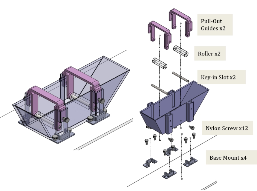
As stated previously, submersion-based impregnation was chosen to be the method pursued in this system. A resin chamber was designed to contain the epoxy resins utilized in impregnation. This chamber has guide slots and holes to secure the two submerged rollers seen in the design in Figure 28 below. These guide slots allow for easy access to the submerged rollers. As these rollers, in particular, are to be replaced routinely after each operation cycle, a pulling mechanism is created to facilitate this process. This allows for the interchangeability of the rollers without having to physically reach into the resin chamber to access the rollers. The resin chamber is also easily detached as it is not fastened to the build tray or ground. Instead, four base mounts are implemented to prevent the chamber from translating when in use. These base mounts also allow for the chamber to slide out and detach from the rest of the system to facilitate the disposal of excess resin. The base is friction fitted to the base mounts and has no risk of lifting off when the tow is passed through the system as tension through the material should be minimized as stated previously. In addition to this, the weight of the chamber and the contained resin coupled with the friction between the interfacing surfaces between the mounts and chamber walls is enough to secure it in place. This system consists of two rollers with corresponding slotted axles and handles, the resin chamber, four base mounts, and 12 fasteners.
The final major subsystem in the group's experimental setup is the squeegee and resin slide system. This subsystem consists of two adjustable squeegees, one roller/axle, a slide body, a snap-it fixture for the roller, and a base. This system was perhaps the most challenging to draft and also was the subsystem with the most areas for improvement or further development. The purpose of this subsystem was to remove excess resin from the tow by passing it through two squeegees with an adjustable aperture. The excess resin is also directed back into the resin chamber by the slide feature seen on the main body of the system. Due to the complexity of component overhangs, thin features, and precise geometries, errors formed during the 3D-printing process. An example can be seen in Figure 29 below.
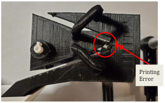
Although components were still able to function as intended, small inaccuracies were identified where the squeegees insert into the body. This causes inaccuracies in the aperture width between the sliders. This was remedied by compressing the squeegees together as the squeegee material is easy to elastically deform. The group suggests that the slide body be manufactured using SLA or other liquid-based additive manufacturing processes as these processes have a higher surface finish as well as come with soluble support material. Some of the inaccuracies observed were also a result of the excess support material that bonded to the main body of the component. A labeled assembly and exploded view of this subsystem can be seen in Figure 30 below.
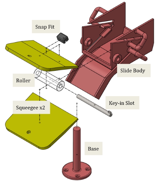
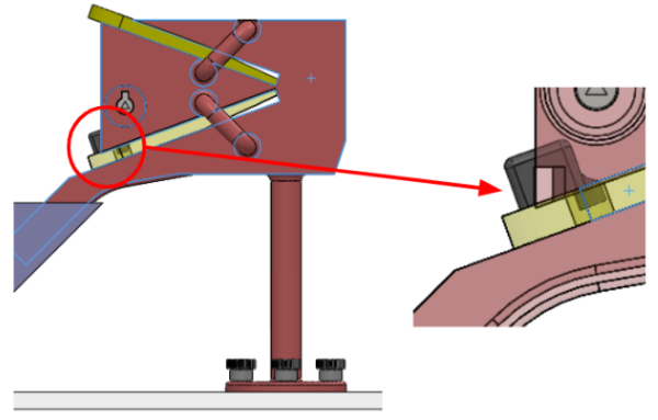
A problem resolved in the design process of this subassembly was one pertaining to the bottom squeegee. It was noticed early on that the bottom squeegee needed to be secured to the slide body. It was preferable to avoid fasteners on this part as the group did not want to modify the bottom squeegee design. The solution implemented was using a snap-it fastener that utilized the hole present in the middle of the squeegee. This snap-it mechanism, seen by the black component in Figure 31, was fixed to the slide body and held the squeegee in place without the need for a traditional fastener. This would allow easy replacement of squeegee components if required in the future.
Manufacturing and Assembly
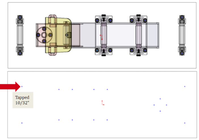
Once the virtual design was inalized, the team moved to fabricate and assemble the components. The majority of component fabrication was completed using FDM printing. A total of 640 grams of PLA was used to fabricate all components. Components were designed with 30 percent infill and two layers of wall filament. The non-printed components were all sourced from McMaster Car which includes the following: nylon thumbscrews (total of 20 used in the design), plastic squeegees, and 10ft of acrylic tubing (10 inches used design). A full component list can be found in the appendix below. The mounting plate that fixed the components was made of an acrylic pane. Mounting holes were tapped so that all the 3D-printed components can be fastened in place. The team used a programmable drill press to tap the holes in the build plate. The CAD model was used to evaluate the distances between mounting holes. This process can be seen in Figure 32 below. The thread size of the holes was 10/32 inches.
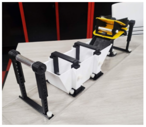
The final assembly of the experimental setup can be seen in Figure 33 below. The experimental setup was successful and minimal error was encountered during prototype fabrication. The printed components and subsystems all were compatible with one another as proper clearance and tolerancing of components accounted for during the design phase avoided downstream manufacturing issues. This was achieved by applying a clearance of 0.1 inches to many 3D-printed components. Some parts were sanded to reduce the friction between interfacing parts, but ultimately all were compatible. The acrylic rollers were cut to size using a band saw and rough edges were also smoothed by sanding.
Although a success, certain areas of the design can be improved, most notably the slide portion of the design as previously discussed. The snap-it mechanism at the slide could be further optimized as the actuation of the snap-it is a bit difficult. This can be easily remedied by increasing the length of the snap-it section that interfaces and holds the squeegee in place. In addition to this, the key-in slot axles for the input and output rollers were not implemented due to the features being too fine for the printer to fabricate accurately. This error did not have any negative implications on the prototype setup, as there was enough friction between the axle and holder to prevent the axle itself from spinning.
Experimental Testing Setup
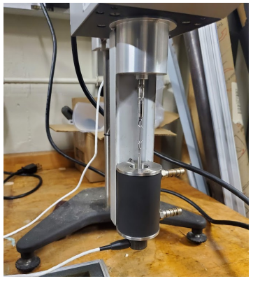
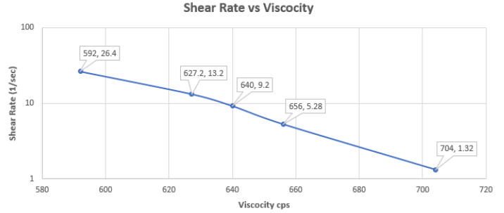
With the assembly completed and the prototype functional, experimentation of prototype performance was completed. The main aspects the group wanted to evaluate were the effectiveness of fiber impregnation and preservation of tow width post impregnation. With the assembly completed and the prototype functional, experimentation of prototype performance was completed. The main aspects the group wanted to evaluate were the effectiveness of fiber impregnation and preservation of tow width post impregnation. Prior to testing, an investigation into the behavioral properties of epoxy resin was needed. To reduce the complexity of experimental testing, a more readily available fluid was used as a substitute. Real epoxy was not used for testing because the curing nature of the fluid may cause damage to the experimental setup and impact the repeatability of experimentation using the same setup. The selected fluid was a sugar syrup, however, testing was needed to verify if this was an acceptable choice. The main component that required similarity was the viscosity. For reference, FibreGlast Epoxy 4600, a commonly used epoxy for such applications, has a viscosity of 575 cps. The regular syrup was found to have a similar viscosity and was subsequently tested for its viscosity at different shear rates using a viscometer. Figure 34 shows the viscometer, and Figure 35 shows the results of this viscosity experiment. At low speeds, the viscosity of regular syrup matches that of the operating viscosity of the epoxy mentioned before, so this was a suitable testing resin. The resulting plot also suggests that the syrup is sheer thinning which is also desirable as a key characteristic of epoxy resins is that they are primarily shear-thinning fluids.
After the station was manufactured and fully assembled, experimentation of performance could begin. To begin the experimentation, fiber tow needed to be pre-spread in order to be fully impregnated by the testing fluid. This was done by slowly rolling about 5 feet of tow onto a tube from the spreader station with a diameter of around 1 inch. This was where the "dry" roll of carbon fiber tow would start. To ensure an easy and controlled feed rate, the other side of the tow would be spooled onto an identical tube; this would be where the "wet" fiber tow would end up.
Next, the station was clamped to a table to prevent any motion induced by the movement of the fiber tow. Once fastened, a few parts of the station were disassembled so that the tow could be easily spooled through; the disassembly included the two resin chamber rollers, top squeegee-slide, and adjustable end roller. The resin chamber rollers, squeegee slide, and end roller were then fastened back into place, and the tow was given slight tension to ensure that the rollers were holding it in place. The syrup was poured into the resin chamber until the tow was visibly below the fill line. The final setup is shown in Figure 36 below.
When the setup was complete, the "wet" tow was rolled and pulled at different speeds onto the end tube by hand by one team member at a constant rate, while another team member provided slight resistance on the start tube with the "dry" tow. The fiber tow was then rolled off of the end tube and evaluated for qualities such as saturation, motion method (pull vs. roll), motion speed (fast vs. slow), and tow width. The first and last foot of the tow was not considered as the first foot of the tow was dry and the last foot was not under tension.
Results
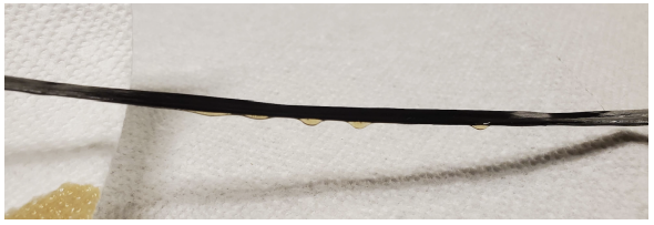
All results related to impregnation are discussed below. Upon evaluation of the saturation, it was noticed that while the tow was fully impregnated with no dry spots, there was an excess of resin along the length of the tow. While the squeegee-slides were able to remove some of the excess resin, it was evident that they were not completely successful. The excess resin resulted in dripping along the end tube and the length of the tow as it was being moved through. However, the resin chamber was successful at fully soaking the fiber tow. A sample of impregnated fiber tow is shown in Figure 37 below.
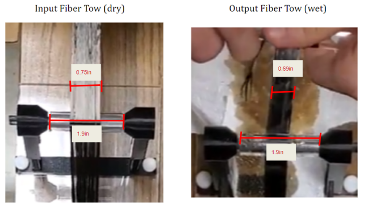
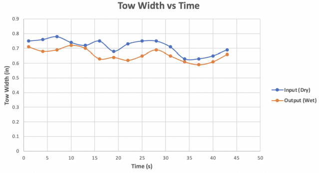
The second parameter evaluated was the effect of impregnation and feed method on tow width. The best feeding method and feed rate were rolling the tow onto the end tube at a slow and constant speed; this was recorded as ~1 inch per second. This resulted in the smallest differences between the pre- and post-impregnation tow width. It was noted that pulling the tow or fast feed rates made the tow shrink in width very quickly. With the most optimal method, the tow width showed an average deviation of 0.095 inches or an 8.2% difference in tow width. This is shown in the Figures below. This was evaluated by videoing the pulling process from the top view and then using the length of the roller, known to be 1.9 inches, to determine the relative length of the tow at the input and output positions (wet or dry). This process can be seen in Figure 38 below. A graph of the dry tow and wet tow at 12-time intervals in which the tow was pulled through the impregnation station can be seen in Figure 39 below.
Conclusion and Next Steps
The compilation of our results yielded a lot of insight into the inner workings of our tow impregnation station. The resin chamber design chosen proved to be too effective at fully saturating the carbon fiber tow with the epoxy resin. This was evident based on the presence of accumulated epoxy resin on the edges of the tow and the subsequent dripping which occurred as a result. To alleviate this, it was concluded that a smaller aperture between the two squeegees would greatly help by forcing the resin to strain off the tow even more. Another viable solution would be to add a second pair of squeegees in series to serve as a backup measure to the proper straining of the tow.
Another unfavorable result, and perhaps the most important, was the fact that the tow was not able to maintain a constant width throughout the impregnation process. Reiterating the results from the previous section the tow shrank from 0.75 in. to 0.69 in. The team concluded that this result was due to one of two possible causes: non-optimal roller shaper or size and non-constant tow pull rate, inducing varying tension. To address this, the team has come up with the conclusion that elliptical, larger diameter rollers, similar to those designed for fiber spreading, would improve the preservation of tow width throughout the impregnation process. Furthermore, when rolling the partially cured prepreg for storage, it is suggested that the tow be pulled at a constant rate in order to further help alleviate the shrinkage problem.
Commenting on the overall design of the system as a whole, the team was very happy with its modularity and composition of interchangeable parts. Douglas Outdoors will be able to put together a prototype similar to the one described in this report with easily accessible fixtures and far more reliable materials (metals and hard plastics). Furthermore, available designs are easily translatable to 3D printers and therefore would be a worthwhile investment for the company. This would allow for rapid prototyping, design changes, and repairs. It is believed that the designs put forth through this research can provide valuable insight for Douglas Outdoors in their desire to transition to in-house prepreg manufacturing.
References
[1] Figure 1 image: https://www.calitzler.com/prepreg-systems/
[2] Fiberglast 4600 spec sheet: https://s3.amazonaws.com/cdn.ibreglast.com/downloads/04160.pdf
[3] Matsuzaki, R., Ueda, M., Namiki, M. et al. Three-dimensional printing of continuous-fiber composites by in-nozzle impregnation. Sci Rep 6, 23058 (2016). https://doi.org/10.1038/srep23058 [4] John P. Coulter, Selcul I. Guceri, Resin impregnation during composites manufacturing: Theory and experimentation,
Appendix